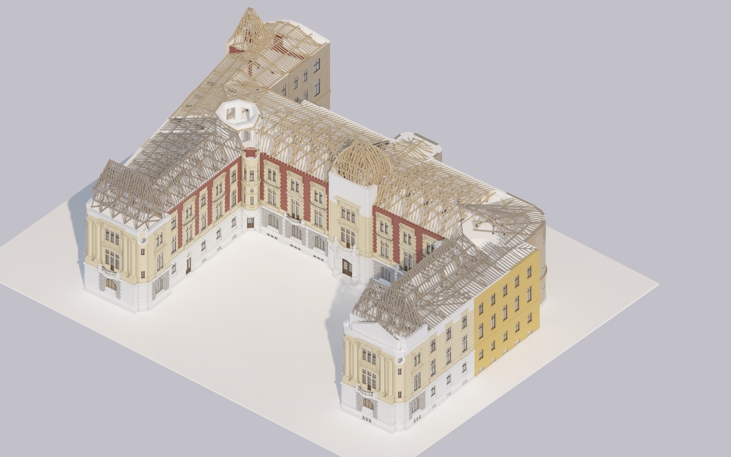
It matters most where the as-built documentation is missing, outdated or was never updated after successive modifications — which is the normal situation in industrial plants that have been running for decades.
What the survey gives you
- A measurable record of the site: distances, clearances and levels can be checked afterwards without going back on site.
- A basis for design and for Building Information Modelling, so new equipment is designed against the real geometry and not against an assumption.
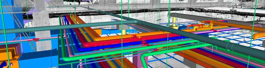
- Clash detection before fabrication: routing a new duct or pipe run through an existing plant room is verified on the model rather than discovered on site.
- Evidence of deviation: facade, structural or installation problems show up as measurable differences and can be addressed before they become failures.
- A permanent record of the site as it was on the day of the survey.
How the survey is carried out
The scanner is set up on a tripod at fixed stations. Successive areas are captured with overlap of at least one third between stations, so the individual scans can be registered into a single coordinate system. The station positions are chosen according to what has to be measured and what obstructs the line of sight.
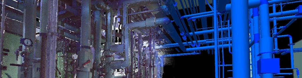
Measurement accuracy is in the order of 5–10 mm over 50 m on the raw point cloud. When the cloud is retopologised into a 3D model — where measured sections are standardised to nominal sizes — the final tolerance is at least ±2%, because remodelling replaces real, non-uniform sections with standard ones.
This distinction matters in practice. If a pipe in service no longer has a constant cross-section, the deviation is readable in the raw scan but is rectified in the modelled geometry. The same applies to bend radii that have drifted from their nominal values. Where a survey is used for fabrication, the raw cloud is the reference; where it is used for layout and coordination, the model is.
A worked example: steam pipework from boilers to turbines
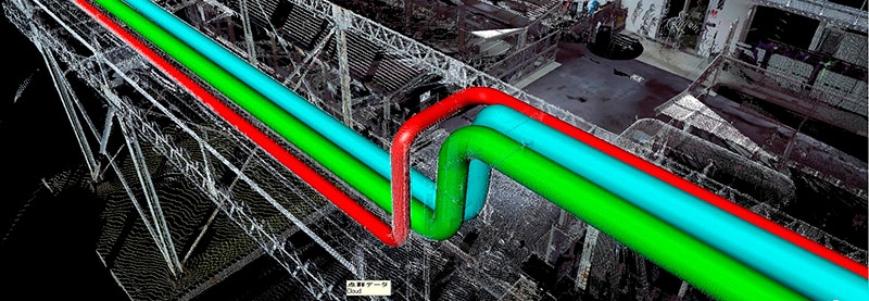
The task was to measure, with high precision, the high-temperature water and steam lines running from the boilers to the turbines and turbo-blowers. Given the complexity of the insulated runs involved, laser scanning was chosen over conventional measurement: it captures the whole volume at once, including sections that are difficult to reach with a tape or a total station.
The centreline of the connection points between pipe sections was preserved and the overall envelope of each segment was respected, so that the resulting survey can be used directly for design of modifications and for coordination with the surrounding plant.
Where we use it
Before refurbishing an existing plant, when the drawings no longer match reality. Before installing new equipment in a congested plant room. For as-built documentation at handover. And in combination with our non-destructive testing laboratory and drone thermal imaging, where the geometry has to be correlated with the condition of the material.